Radar Signal-Processing System-on-Chip: Architecture, Applications, Design Approach and Verification
RF & Mixed-Signal Design · DSP Architecture · Sensor SoC Verification
Radar is being used as a specialized sensing technology in aerospace, defense, automotive, robotics, drones, smart infrastructure, and consumer applications. Modern radar systems are expected to detect objects, estimate distance and velocity, determine direction, classify targets, and operate reliably in challenging environmental conditions such as darkness, fog, rain, and dust.
The growing demand for compact, low-power, and intelligent radar has created a strong need for highly integrated Radar System-on-Chip (Radar SoC) architecture. A Radar SoC integrates the RF front end, data converters, signal-processing engines, processor subsystem, and their interface functions into a single semiconductor platform.
A Radar Signal-Processing SoC
A well-designed Radar SoC bridges two fundamentally different engineering domains: the analog/RF portion, which must preserve extremely weak high-frequency signals with excellent noise, linearity, phase, and frequency performance, and the digital portion, which processes enormous volumes of sampled data with deterministic latency and high computational efficiency. Successful Radar SoC development therefore requires coordinated analog, RF, mixed-signal, digital, architecture, physical-design, software, and verification expertise.
A Radar SoC is a complete sensing and computing platform that receives reflected electromagnetic signals from the environment and converts them into meaningful information about objects and their motion.
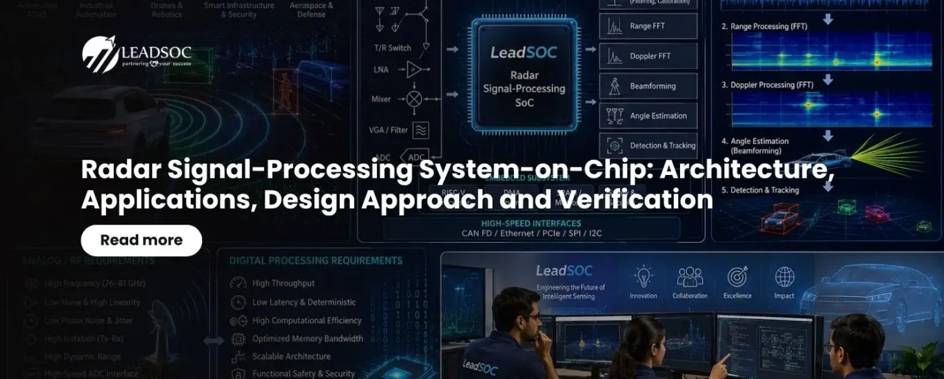
A typical radar signal chain starts with a frequency synthesizer and transmitter that generates a radar waveform. The transmitted signal propagates through the antenna and interacts with objects in the environment. A portion of the reflected signal is captured by one or more receiving antennas, amplified, and down-converted before high-speed ADCs convert it into digital samples.
The digital processing subsystem then performs operations such as digital filtering, Fast Fourier Transform (FFT), Doppler processing, beamforming, angle estimation, target detection, and tracking. A processor or dedicated accelerator subsequently interprets these results and provides information to an application processor, vehicle controller, industrial controller, or external host. The fundamental objective is not simply to process radar samples faster — the SoC must maintain the integrity of the signal chain from the antenna through RF and analog processing into the digital domain, ultimately delivering reliable sensing information with predictable latency and power consumption.
Applications of Radar SoCs
Automotive Radar
Automotive radar is one of the most important applications for Radar SoCs. Radar sensors are used for adaptive cruise control, automatic emergency braking, blind-spot detection, lane-change assistance, rear cross-traffic detection, parking assistance, and other advanced driver-assistance functions.
Modern vehicles increasingly use multiple radar sensors positioned at the front, rear, and corners of the vehicle. Short-range radar can provide wide-area coverage around the vehicle, while long-range radar can detect objects hundreds of meters away depending on the radar architecture and operating conditions. Processing requirements become particularly demanding when multiple transmit and receive channels are used to obtain high angular resolution — MIMO radar architectures can create a larger virtual antenna array, increasing the system's ability to distinguish objects that are close together in angle.
Industrial and Factory Automation
Industrial radar can be used for level measurement, object detection, material monitoring, machine protection, and process control. Radar has an advantage over many optical sensing technologies because its operation is less dependent on lighting conditions and can tolerate environments containing dust, smoke, or vapor. A Radar SoC for industrial applications may prioritize very high measurement accuracy, low power, long operating lifetime, and deterministic behavior rather than the extremely high computational throughput required by automotive perception systems.
Drones and Robotics
Radar provides robots and unmanned aerial systems with sensing capabilities that complement cameras and LiDAR, assisting with obstacle detection, altitude measurement, navigation, and motion estimation. For battery-operated platforms, the Radar SoC must provide substantial processing capability while maintaining a very low power budget, making hardware acceleration and efficient memory architecture particularly important.
Smart Infrastructure and Security
Radar SoCs can also support traffic monitoring, pedestrian detection, perimeter monitoring, and occupancy sensing. Since radar can detect movement without requiring visible light, it can operate continuously during both day and night.
Aerospace and Defense
Radar remains fundamental to surveillance, tracking, navigation, and target detection. These applications require sophisticated beamforming, high dynamic range, multiple simultaneous channels, and specialized signal-processing algorithms. Although application requirements vary considerably, the underlying SoC challenge remains similar: accurately acquire weak RF signals and transform them into useful spatial, range, and velocity information with high reliability.
Sensing the Radar Signals
One of the commonly used approaches in modern radar is Frequency-Modulated Continuous Wave (FMCW) radar. In an FMCW system, the transmitter generates a controlled frequency sweep, commonly referred to as a chirp.
When the chirp is reflected from an object, the received signal experiences a time delay proportional to the distance of the object. The received signal is mixed with a reference version of the transmitted signal to generate a beat frequency, which contains information related to target range. If the target is moving, Doppler shift introduces an additional frequency component; by observing changes in the beat signal over multiple chirps, the radar can estimate target velocity.
Multiple receiving antennas provide spatial information. The phase differences between signals received by different antennas can be processed to estimate the direction from which the signal arrived. Combining range, velocity, and angular information produces a three-dimensional radar representation of the environment. The digital processing chain therefore commonly progresses from ADC samples to range information, then Doppler information, followed by angle estimation and finally object detection and tracking.
Radar SoC Architecture
A representative Radar SoC consists of an RF front end, analog signal-conditioning circuitry, data converters, digital signal-processing accelerators, a memory subsystem, an embedded processor, safety and security functions, and external interfaces.
The RF front end contains the transmit and receive signal paths, frequency synthesizer, power amplifiers, low-noise amplifiers, mixers, and associated high-frequency circuitry. The analog section interfaces these circuits to ADCs and DACs where applicable.
The digital subsystem receives high-rate sample streams and performs computationally intensive operations. FFT engines, digital filters, beamforming accelerators, matrix-processing engines, and detection accelerators can be implemented as dedicated hardware blocks. An embedded processor manages configuration, diagnostics, calibration, communication, and higher-level algorithms, and the SoC may also contain DMA engines, SRAM, cache, external-memory interfaces, and high-speed communication interfaces.
The architecture must be designed around the complete data path rather than treating each block independently. A high-performance FFT accelerator is of limited value if the memory subsystem cannot feed it with data at the required rate, and an excellent RF receiver cannot deliver good system performance if clock jitter, ADC performance, or digital quantization limits the overall signal-to-noise ratio.
Analog and RF Design Requirements
The analog/RF portion of a Radar SoC has fundamentally different requirements from the digital processing subsystem. At radar frequencies, parasitic capacitance, package effects, transmission-line characteristics, electromagnetic coupling, and power-supply noise can significantly affect performance.
For automotive radar, the RF front end commonly operates in the 76–81 GHz frequency region. At these frequencies, transistor models, passive components, routing structures, and package interconnects must all be considered as part of RF design. The receiver requires adequate gain and low noise so that weak reflected signals can be detected, the transmitter requires sufficient output power while maintaining spectral purity and linearity, mixers must provide suitable conversion gain and isolation, and the frequency synthesizer and PLL must provide excellent phase-noise performance.
The ADC interface is particularly important because the analog signal must be converted into the digital domain without losing the information needed for range, velocity, and angle estimation — ADC resolution, sampling rate, aperture jitter, linearity, dynamic range, and clock quality therefore have a direct impact on radar performance. The analog/RF design must also address isolation between transmitter and receiver paths, since leakage from a powerful transmitter into a sensitive receiver can reduce dynamic range and make detection of nearby weak targets difficult.
Digital Processing Requirements
The digital subsystem has a different optimization objective: processing large amounts of sampled radar data efficiently, deterministically, and with sufficiently low latency. A typical processing chain can include digital filtering, DC-offset removal, windowing, range FFT, Doppler FFT, clutter suppression, beamforming, angle FFT or other spatial processing, detection, and target tracking.
Computational requirements can become substantial when the radar has many transmit and receive channels — an MIMO radar with multiple antennas can generate a large virtual array and correspondingly increase the amount of data that must be processed. Dedicated hardware accelerators are therefore often preferred for repetitive mathematical operations: FFT accelerators, multiply-accumulate arrays, vector processors, and configurable DSP engines can provide significantly better performance per watt than executing every operation on a general-purpose processor.
Memory architecture is equally important, since radar processing involves continuous movement of large sample matrices between ADC interfaces, SRAM, accelerators, and processors. Local SRAM, DMA engines, multi-bank memories, and carefully designed data paths can reduce memory bottlenecks and energy consumption. The digital subsystem must also provide deterministic latency where radar information feeds safety-critical or real-time control functions, so the architecture should define throughput, latency, memory bandwidth, clock domains, and buffering requirements before RTL development begins.
Co-Design of Analog/RF and Digital Subsystems
Radar SoC development should begin with system-level requirements rather than individual IP blocks. The radar range, resolution, velocity range, angular resolution, number of channels, chirp configuration, operating frequency, environmental conditions, and power budget establish the fundamental architecture.
The analog/RF architecture should first determine the transmitter and receiver configuration, antenna interface, frequency-generation architecture, gain distribution, noise budget, linearity requirements, and data-converter requirements. RF link-budget analysis and system-level simulations are essential for determining whether the receiver can reliably detect the expected target signals. At the same time, the digital architecture should derive the required ADC sample rate, data throughput, processing operations, memory bandwidth, and accelerator requirements. Algorithm models using MATLAB, Python, C/C++, or equivalent modeling environments can be used to determine the required numerical precision and processing complexity before committing to hardware.
The boundary between analog and digital processing should be carefully optimized. Moving more processing into the digital domain can provide programmability and calibration flexibility, but it increases ADC requirements and digital power. Performing more operations in analog can reduce digital data volume but may reduce flexibility and introduce accuracy challenges. The best architecture is therefore a balanced partition between RF, analog, mixed-signal, and digital processing.
Radar Algorithm Development and Hardware Mapping
Radar algorithms should initially be developed as floating-point reference models that reproduce the complete signal chain, from transmitted waveform and target reflection through receiver processing and target detection.
Once the algorithm is validated, fixed-point analysis can determine the numerical precision required for hardware implementation. This step is particularly important for FFTs, beamforming, correlation, filtering, and detection algorithms, because excessive quantization can degrade sensitivity while excessive precision increases area, power, and memory requirements.
Computationally intensive and repetitive portions of the algorithm can then be mapped to hardware accelerators, while functions that require frequent algorithmic updates or application-specific configuration can remain programmable. This approach creates a heterogeneous Radar SoC in which dedicated accelerators provide high performance, while embedded processors provide flexibility and system control.
Clocking, Synchronization and Data Movement
Clock architecture is critical because radar signal processing involves high-speed ADCs, RF synthesizers, digital accelerators, and multiple processing domains. RF and data-converter clocks require extremely low jitter because timing uncertainty can directly degrade signal-to-noise performance, while digital processing clocks are optimized primarily for throughput, power, and timing closure.
Clock-domain crossings between ADC interfaces, processing engines, memory, and processor subsystems must be explicitly designed and verified. FIFO-based synchronization, handshake mechanisms, and carefully controlled reset architectures are essential. Data movement should be treated as an architectural problem rather than simply an RTL implementation detail — DMA engines, buffering, memory banking, and NoC or bus architecture must be sized according to the radar data rate and processing pipeline.
Functional Safety and Security
Radar sensors increasingly participate in safety-critical automotive functions. Consequently, the SoC architecture may need mechanisms such as error detection, memory protection, watchdogs, redundant monitoring, built-in self-test, diagnostic coverage, and safe-state handling. Depending on the target application and safety concept, hardware may need to support requirements associated with automotive functional-safety standards such as ISO 26262.
Security is also becoming important because radar sensors communicate with other electronic control units and may be exposed to external interfaces. Secure boot, hardware cryptographic acceleration, authentication, debug protection, and secure firmware update mechanisms can be incorporated according to system requirements.
Verification Strategy for Radar SoCs
Radar SoC verification must extend beyond conventional RTL functional verification because system performance depends on interactions between RF, analog, mixed-signal, and digital domains.
The digital processing architecture can first be verified against a golden reference model, applying identical radar input vectors to the reference algorithm and RTL implementation and comparing outputs for numerical accuracy, detection performance, and latency. Constrained-random verification and UVM-based environments can verify control logic, register interfaces, DMA operation, memory access, interrupts, error handling, and accelerator functionality, while assertions check protocol behavior, FIFO properties, state-machine correctness, and safety mechanisms.
The DSP accelerators require dedicated verification because numerical errors can be difficult to identify using conventional binary pass/fail tests. FFT, filtering, beamforming, and detection blocks should be compared against high-precision reference models using defined error tolerances.
Mixed-Signal and RF Verification
Analog and RF verification requires a substantially different methodology. SPICE-based simulations can be used for transistor-level analysis of critical circuits such as LNAs, mixers, PLLs, amplifiers, and data-converter interfaces. RF simulations should evaluate gain, noise figure, phase noise, linearity, compression, isolation, frequency response, and other application-specific parameters, with process-voltage-temperature corners included to understand worst-case behavior.
Electromagnetic simulation can become important for antennas, high-frequency interconnects, package structures, and critical passive components, with parasitic extraction incorporated into post-layout simulations because physical implementation can significantly affect high-frequency behavior. Mixed-signal co-simulation is useful for validating the interaction between analog blocks and digital processing — for example, ADC imperfections such as quantization noise, offset, gain error, nonlinearities, and jitter can be introduced into a digital radar model to determine their impact on detection performance.
System-Level Radar Verification
A complete Radar SoC should ultimately be verified using realistic radar scenarios rather than isolated synthetic test vectors. A system-level verification environment can generate virtual targets with configurable range, velocity, radar cross-section, angle, and noise characteristics, including multiple-target scenarios to evaluate the processing chain's ability to distinguish objects that are close in range, velocity, or angle. Environmental impairments such as thermal noise, interference, clutter, multipath, and phase or amplitude mismatches can be introduced to evaluate algorithm robustness.
Hardware-in-the-loop and FPGA-based prototyping can provide an intermediate step between simulation and silicon, allowing real radar data to be captured and replayed through the digital processing chain to validate throughput, latency, and algorithm behavior under realistic conditions. Post-silicon validation should then correlate measured RF and ADC performance with pre-silicon models, passing radar data captured from silicon through the complete processing chain to determine whether range, velocity, and angle estimation meet the original system specifications.
Physical Design Challenges
Radar SoC physical implementation introduces challenges that are not normally encountered in a conventional digital SoC. High-speed digital switching can generate power-supply noise and electromagnetic interference that can affect sensitive analog and RF circuitry. The floorplan must therefore provide appropriate isolation between RF, analog, high-speed digital, and noisy clocking regions, with power domains, ground structures, shielding, and guard rings designed according to the technology and RF architecture.
For high-frequency radar, package and PCB design become part of the overall electrical system — RF routing, antenna connections, thermal behavior, and power delivery must be analyzed together with the silicon implementation. Digital physical design must simultaneously achieve timing closure, power targets, and sufficient routing resources for high-throughput processing engines and memories, and low-power techniques such as clock gating, power gating, and optimized data movement can substantially reduce overall energy consumption.
A Practical Radar SoC Development Flow
A robust development flow begins with system requirements and radar performance modeling. The next stage defines the RF and analog architecture alongside the digital signal-processing architecture. Reference radar algorithms are then developed and validated using high-level models, with hardware/software partitioning and accelerator selection following computational profiling.
The analog/RF design proceeds through schematic design, simulation, layout, extraction, RF and electromagnetic analysis, and silicon-oriented verification. In parallel, digital blocks proceed through microarchitecture, RTL design, functional verification, synthesis, DFT, physical implementation, timing analysis, and power analysis. The complete system should be brought together through mixed-signal simulation, virtual prototyping, FPGA emulation, and hardware-in-the-loop testing wherever practical. Continuous correlation between system models and implementation measurements is important, because small assumptions made at one abstraction level can create significant system-level errors.
The Role of Reusable IP in Radar SoC Development
Reusable IP can significantly reduce development time when the architecture is built around well-defined interfaces and configurable processing blocks. FFT engines, DMA controllers, memory controllers, processor subsystems, safety monitors, communication interfaces, and hardware accelerators can be designed for reuse across radar generations and applications.
However, reuse should not be limited to RTL. Verification environments, reference models, firmware drivers, test vectors, and coverage models can also become reusable assets. A mature Radar SoC development methodology therefore treats both design IP and verification IP as strategic building blocks.
Radar SoC Applications at a Glance
| Application Domain | Typical Use Cases | Key Design Priority |
|---|---|---|
| Automotive | Adaptive cruise control, AEB, blind-spot detection, parking assistance | High angular resolution, MIMO channels, functional safety (ISO 26262) |
| Industrial & factory automation | Level measurement, object detection, machine protection | Measurement accuracy, low power, deterministic behavior |
| Drones & robotics | Obstacle detection, altitude measurement, navigation | Low power budget, hardware acceleration, compact form factor |
| Smart infrastructure & security | Traffic monitoring, pedestrian detection, perimeter sensing | Day/night operation, continuous monitoring |
| Aerospace & defense | Surveillance, tracking, navigation, target detection | Beamforming, high dynamic range, multi-channel processing |
Conclusion
A Radar Signal-Processing SoC is a highly integrated combination of RF sensing, mixed-signal conversion, high-throughput digital processing, and intelligent decision-making. Its success depends on much more than implementing a collection of individual IP blocks.
The analog/RF domain must provide low-noise, high-linearity, and phase-accurate signal acquisition, while the digital domain must transform enormous volumes of sampled data into range, velocity, and angular information with high performance and low power. The interface between these two domains is one of the most critical architectural boundaries in the entire system.
For automotive, industrial, robotics, and other emerging applications, the trend is toward increasingly integrated radar platforms with more channels, higher angular resolution, greater processing intelligence, and stronger functional-safety requirements. This makes system-level architecture, hardware acceleration, mixed-signal modeling, verification, and physical implementation expertise essential.
A successful Radar SoC program therefore requires a methodology that connects RF design, analog signal conditioning, ADC, digital signal processing, hardware acceleration, embedded software, target detection, and system validation as one continuous engineering flow. For organizations developing advanced sensing SoCs, expertise in reusable IP development, RTL and verification, DSP accelerator design, physical implementation, mixed-signal integration, and system-level validation can significantly reduce development risk and accelerate the path from radar concept to production silicon.
Stay Connected with LeadSOC
LeadSOC continues to focus on AI-enabled practical semiconductor design methodologies and reusable SoC technologies for emerging high-performance applications. Subscribe to LeadSOC for more engineering-focused articles covering advanced SoC architecture, AI-assisted semiconductor design, automotive electronics, RF and sensor interfaces, verification, and silicon implementation.
Subscribe Now