Simulation is one of the most critical stages in semiconductor design. Before a chip reaches fabrication, designers must verify that the design behaves as intended under different operating conditions. Since fabricating an integrated circuit involves significant cost and time, simulation provides a controlled and cost-effective way to validate functionality and performance.
Simulation plays a central role in the design and verification flow, enabling teams to validate complex SoC architecture, IP blocks, and system interactions long before tape-out.
The Concept of Simulation in Digital Design
Simulation is the process of executing a hardware model in a software environment to observe its behavior over time. Digital systems, typically described using hardware description languages (HDLs) such as Verilog, SystemVerilog, or VHDL. Simulation tools interpret or compile these descriptions to emulate the behavior of digital circuits.
Through simulation, engineers can:
- Verify functional correctness of RTL designs
- Detect design bugs early in the development cycle
- Validate interactions between multiple IP blocks
- Analyze protocol compliance and corner cases
- Evaluate design performance before hardware implementation
Simulation therefore forms the foundation of functional verification, which typically accounts for the largest portion of the semiconductor development cycle.
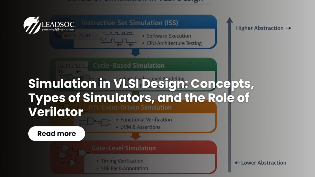
Types of Simulators Used in VLSI Design
Modern semiconductor systems are extremely complex and are verified at multiple abstraction levels during development. As a result, different types of simulators are used throughout the design flow, each addressing a specific level of design abstraction and verification need.
Instruction Set Simulators (ISS)
Instruction Set Simulators operate at the highest level of abstraction in the hardware development stack. Instead of modeling hardware structures such as logic gates or RTL signals, an ISS models the behavior of a processor by executing instructions defined in its architecture.
An ISS emulates how a CPU executes instructions from a program according to its instruction set architecture. This capability allows software developers to write and test firmware, operating systems, and application software long before the actual hardware implementation becomes available.
Instruction set simulators are particularly important in processor-centric designs and embedded systems development. They enable early software development, architecture validation, and performance analysis of software workloads. Because they operate at a high abstraction level, ISS platforms can run significantly faster than RTL simulations and allow extensive software debugging prior to silicon availability.
Instruction set simulators are widely used in processor ecosystems such as RISC-V and ARM. Common ISS tools include Spike for RISC-V architectures, QEMU for system-level processor simulation, and Imperas OVPsim for architectural modeling.
RTL (Register Transfer Level) Simulators
RTL simulators operate at the logical design level where digital circuits are described in terms of registers, data paths, and control logic. In this abstraction, designers specify how data moves between registers and how logic operations are performed under the control of clock signals.
RTL simulation is primarily used to validate the functional behavior of digital logic. It enables engineers to verify control logic, arithmetic units, communication interfaces, and protocol implementations before synthesis. Verification environments built using methodologies such as UVM rely heavily on RTL simulation to execute test benches, assertions, and coverage-driven verification strategies.
Because RTL simulation focuses on logical functionality rather than physical implementation details, it provides a good balance between simulation speed and design visibility.
Gate-Level Simulators
Gate-level simulators operate on the synthesized netlist generated after the logic synthesis stage. In this representation, the design is expressed as interconnected logic gates that correspond closely to the final hardware implementation.
Gate-level simulation is often used to validate synthesis results and to confirm that the design operates correctly when mapped to physical logic gates. It is particularly useful for verifying reset behavior, clock gating logic, and design initialization sequences.
Another important application of gate-level simulation is timing verification. By applying Standard Delay Format (SDF) back annotation, engineers can include realistic gate delays and interconnect delays in the simulation model. This helps to validate that the design meets timing constraints before physical implementation.
Although gate-level simulation provides higher fidelity compared to RTL simulation, it is significantly slower and therefore typically used selectively for final verification stages.
Analog and Mixed-Signal Simulators
In many modern SoCs, digital logic must interact with analog components such as data converters, sensor interfaces, PLLs, power management circuits, and communication interfaces. Analog simulators operate at the transistor level and simulate electrical properties such as voltages, currents, capacitances, and transistor switching behavior.
These simulators are essential for validating analog IP blocks, signal integrity, and power behavior. Mixed-signal simulators extend this capability by allowing digital and analog models to run within the same simulation environment.
Mixed-signal simulation is critical in applications such as automotive electronics, IoT systems, wireless communication devices, and high-performance computing platforms where digital control logic interacts closely with analog circuitry.
Cycle-Based vs Event-Driven Simulation
Digital simulators can also be categorized based on how they process signal transitions during simulation. The two primary approaches used in simulation engines are event-driven simulation and cycle-based simulation.
Event-driven simulators track every signal transition that occurs within the design. Whenever a signal changes value, the simulator propagates that change through dependent logic elements and schedules further events accordingly. This approach accurately models circuit behavior because it captures signal transitions occurring at arbitrary points in time, including delays introduced by gates and wires.
Because of this accuracy, event-driven simulation is widely used for RTL functional verification, gate-level simulation with timing back annotation, and verification environments involving asynchronous logic or complex clock interactions. Most commercial simulators use highly optimized event-driven engines to support advanced verification features such as UVM, assertions, and detailed timing analysis.
Cycle-based simulators operate at a higher abstraction level by evaluating the design only at discrete clock boundaries. Instead of tracking every signal transition, the simulator updates the state of the design once per clock cycle. This approach assumes that most logic activity occurs synchronously with the clock edge.
Since cycle-based simulators perform fewer computations, they can execute simulations significantly faster than event-driven simulators. They are therefore widely used in architectural exploration, processor modeling, large regression environments, and hardware-software co-simulation platforms.
In practice, many development flows combine both approaches. Cycle-based simulation is used for rapid development and large-scale testing, while event-driven simulation is used for detailed functional verification and timing analysis.
Commercial Simulation Tools from EDA Vendors
Several EDA vendors provide high-performance simulation platforms designed to support complex semiconductor verification environments.
Synopsys VCS is one of the most widely used RTL simulators in the ASIC industry. It provides high-speed simulation, native SystemVerilog and UVM support, and advanced debugging capabilities. VCS is commonly used in large SoC verification environments that require scalable regression testing and coverage-driven verification.
Cadence Xcelium is another widely adopted simulation platform that supports RTL, gate-level, and mixed-signal verification within a unified environment. It provides scalable parallel simulation engines and integrates tightly with Cadence verification tools and debugging infrastructure.
Siemens Questa, formerly known as ModelSim, is widely used in both ASIC and FPGA verification environments. It supports mixed-language simulation, assertion-based verification, and advanced debugging capabilities. Questa is particularly popular in academic environments as well as industrial design flows.
Aldec simulators such as Riviera-PRO and Active-HDL are also widely used, particularly in FPGA development environments. These simulators support mixed-language designs and integrate well with FPGA synthesis and development toolchains.
Open Source Simulation: Verilator
Alongside commercial EDA simulators, open-source tools have gained increasing importance in recent years. One of the most widely used open-source simulators is Verilator.
Verilator converts Verilog and SystemVerilog designs into optimized C++ or SystemC models that can be compiled and executed as software programs. This compiled simulation model differs from traditional event-driven simulation engines and enables extremely high simulation performance.
Verilator is widely used in open hardware development, academic research, and processor design ecosystems such as RISC-V. Because the generated simulation models are written in C++, they integrate naturally with software frameworks, enabling efficient hardware-software co-simulation environments.
Another advantage of Verilator is its built-in linting capability, which detects design issues such as unused signals, coding style problems, and potential synthesis mismatches during compilation. Being open source, Verilator also allows organizations to customize the simulator to suit specific research or development requirements without licensing constraints.
Major Differences Between Verilator and Commercial Simulators
Although Verilator provides excellent performance and flexibility, it differs significantly from commercial simulators used in large-scale industrial verification flows.
Verilator primarily focuses on high-speed cycle-level simulation by translating RTL designs into compiled C++ models. This approach enables very fast execution speeds but does not naturally support all features required for full verification environments.
Commercial simulators, on the other hand, use sophisticated event-driven simulation engines that support complete verification methodologies, advanced debugging capabilities, mixed-language simulation, gate-level timing verification, and coverage analysis.
As a result, Verilator is extremely useful for rapid functional simulation, open hardware development, processor modeling, and continuous integration testing environments. Commercial simulators remain essential for comprehensive verification flows required for silicon sign-off.
The Role of Simulation in Modern SoC Development
As semiconductor systems grow in complexity, simulation continues to be the backbone of design verification. Modern SoCs integrate billions of transistors, multiple clock domains, heterogeneous compute engines, and complex interconnect architectures. Ensuring functional correctness across such systems requires a robust multi-level simulation strategy.
A comprehensive simulation environment typically includes instruction set simulators for early software development, cycle-based simulators for architectural exploration, RTL simulators for functional verification, and gate-level or analog simulators for implementation validation.
Together with hardware emulation and FPGA prototyping, these simulation technologies allow engineers to detect design issues early, reduce development risk, and accelerate time to market.
At LeadSOC, simulation-driven verification forms an integral part of the design methodology, enabling the development of reliable semiconductor solutions while minimizing costly silicon re-spins.
In our next blog we shall cover Simulation, Emulation and FPGA prototyping. If you are curious about the SOC verification, subscribe to LeadSOC blog and visit www.leadsoc.com for joining us if you want to challenge yourself.